 Professor V. S Medvedev(1), S. M. Korsun(1),
 S.V. Makhalov(1), V. Robtsov(1)(photo), Dr. B. S. Dalay (2). 1. Moscow State Technical University, (named after N.E.Bauman), Russia. 2. De Montfort University, Leicester, UK.
S. M. Korsun1, S.V. Makhalov1, V. Robtsov1.
Abstract
Setting up differential equations for complex dynamic systems such as an open kinematic link manipulator system is a complicated process. It is expedient to automate this process. To solve this problem a new type of building block for SIMULINK was designed. On the basis of the structure, specific values of geometrical dimensions, masses and inertia moments can be investigated without the need to solve the differential equations describing mechanism dynamics each time.
Construction mathematical model of robot's manipulator
Mathematical models of an end effector use differential equations to describe the dynamic properties of the manipulator and it's drives. As manipulators are complex mechanisms with many degrees of freedom the system of differential equations are complicated by a set of the nonlinear equations. Mistakes during initialisation of these relationships can be avoided through systematic approaches. There are several options (See [4],[5]):
Lagrange equation Dalamber principle Newton equations Hamilton principle
The setting up procedure is programmed into the computer. Subsequent use of the computer model constructs the right parts of the equations and carries out any necessary integration. The Matlab-simulink software provides and ideal environment in this respect. Furthermore, computer simulation solves the problem of construction and integration of dynamic equations in to the robot's embedded control system. For this purpose structural models of the drives with designation of control signals and disturbances are being set up. The inputs of the manipulator model are torques for the drives, the outputs of the model are positions and speeds of the links.
Analyzing simulation results, it is possible to discover the possibility of collision with an obstacle, the steps necessary to correct dynamic properties of the drives and other operational features of the manipulator. If need be iterative procedures can be used produce changes in the design. This allows a reduction in the time taken to design which further reduces the cost of the project. Using a mathematical model it is possible test control programs for drive's microcomputers.
Construction of the robot model on the basis of the type 2 Lagrange equations.
The method of automated deriving of the Lagrange equations begins by considering a manipulator as a system of the rigid bodies, jointed together by rotary and linear, fifth class, kinematic pairs that are together an open kinematic chain. The first link is connected with stationary member by a fifth class pair. The last N-th joint is used to mount the end effector which might be a gripper. Manipulator links are numbered sequentially 1,2,...,N. Each link has an associated system of local coordinates. The stationary reference system is associated with the base. Derivation of the mechanical system dynamic equation.
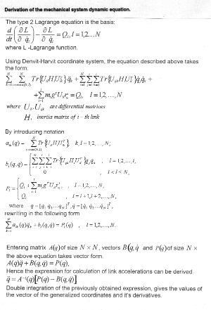
(Click to enlarge then BACK to return) Description of the building block 'ROBOT'.
Using the algorithm described above, a MEX-file was written in using a C-language compiler. This file was then embedded in a S-function block. As the number of parameters for simulation exceeded maximum number of standard input strings for an S-function block, a special-purpose input program had to be constructed. Input of the parameters was based on the principle of floating windows. Inputs were facilitated by using buttons or by typing data in the input strings fields.
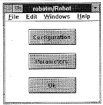
Double clicking the left mouse button on the 'ROBOT' block invoked the main menu (fig.1).
(Click to enlarge then BACK to return)
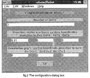
The Configuration button opens a further dialog window. Here it is possible to specify the exact configuration of the system (fig.2).
(Click to enlarge then BACK to return)
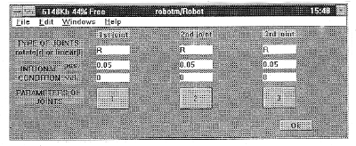
The Number of joints string was used for inputting the number of links. This value changes the number of the block inputs and outputs automatically. The second string serves to input the orientation vector g in projection on inertial coordinate system referenced to the system of the base. The third string serves to input the orientation of the grip reference system in projections on coordinate axis bounded up with N-1 links . Parameters button (fig.1) opens a dialog window to input parameters for each link (fig 3).
(Click to enlarge then BACK to return)
The first string describes the type of the link: (r)-rotary, (l)-linear.
The second and third strings specify the initial conditions for each joint in terms of position and speed. The fourth string contains four buttons to open dialog windows for specifying geometrical and inertial parameters for the link (fig.4). fig.4
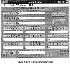
(Click to enlarge then BACK to return)
Once the changes to the parameters have been made, all windows are closed by pressing OK button in the main window menu.
Solution for an example robot manipulator.
To illustrate the capabilities of the model a three-link plane pendulum robot manipulator was selected. Dry friction was assumed to be present in all joints and the physical characteristics selected as follows:
First link: length = 0.3 m; mass = 0.3 kg; initial angle =0.05 rad; Second link: length = 0.2 m; mass = 0.2kg; initial angle =0.05 rad; Third link: length = 0.2m; mass = 0.2 kg; initial angle =0.05;
Pendulum parameters were input by means of the 'ROBOT' building block outlined above. The model was described by the block diagram shown in fig.5
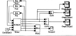
(Click to enlarge then BACK to return)
The results of simulation are shown in fig.6
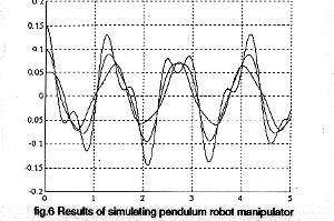
(Click to enlarge then BACK to return)
The work gave following the following results:
An algorithm for automation derivation of dynamic equations relating to open kinematic chain was created
Building block 'ROBOT' for standard SIMULINK library was designed and implemented
Simulation of the number of a pendulum robot manipulator system was demonstrated in SIMULINK by means of the block 'ROBOT'.
References:
1. MATLAB User's Guide. USA, Natick, Mass 1993. - 215 pp.
2. Astrom K. Computer aided modeling, analysis and design of control systems. Perspective, IEEE Control Systems Magazine, Vol. 3, No. 2, May 1983.
3. Simulink User's Guide. USA, Natick, Mass, 1992. - 243 pp.
4. Kulikov F. M., Supervisor control of manipulator robots. M., Nauka, 980, 448 pp.1
5. Medvedev V. S., Leskov A. G., Iushchenko A. S. Control systems of manipulator robots. M., Nauka,1978, 416 pp.
6. Kotov E. A., Scvortsov L. M. Simulation of dynamics of automaticalcontrol systems of multilink manipulator robots. M., MSTU named after Bauman 1986, 17 pp.
7. Paul R. Modeling, trajectory calculation and servoing of a computer controlled arm. Stanford University, 1972, 96 pp.
8. Vicker J.J. Dynamic force analysis of spatial linkages using 4x4 matrices. Trans. ASME, paper no. 66, 1967. 12 pp.
For more SYNDICATE SPEAKERS For other SYNDICATES |